

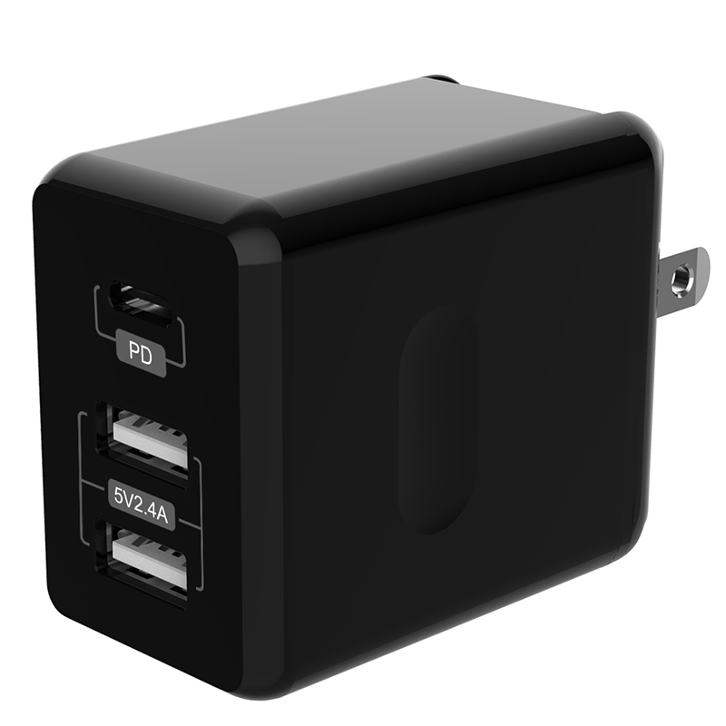
Hot selling Type C +Double USB-A Port PD30W Quick Charger
SPECIFICATION FOR APPROVAL
Product name: PD30W
Model No: MSA056 C+A+A
1、SCOPE:
2.The document detail the electrical, mechanical and environmental specifications of a SMPS, the power supply provide 32W continuous output power.
The power supply shall meet the RoHS requirement.
2.1. Description
2.1. Description
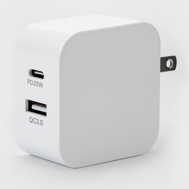
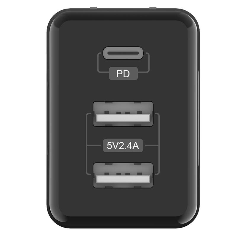
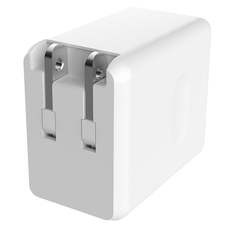
SMPS Adaptor(Wall mount) SMPS Adaptor(Desk-top)
Open Frame USB TYPE C CHARGER
3.Input Characteristics
3.1. Input Voltage & Frequency
|
Minimum |
Nominal |
Maximum |
|
|
Input Voltage |
90Vac |
100Vac-240Vac |
264Vac |
|
Input Frequency |
47Hz |
60Hz/50Hz |
63Hz |
3.2. Input AC Current/AC
1Amax. @ 100-240Vac input & Full load
3.3. Inrush Current (cold start)
40Amax. @ 264Vac input
3.4. Average Efficiency
84%min.Input voltage 100V/240V.
3.5. Energy Consumption /No-load power consumption
When the rated input is 100V/240V, the no-load power
consumption ≤0.15W ( Under no-load )
4.Output Characteristics
4.1. Output Characteristics <Vo & R+N>
|
Output |
Max. Power(Total) |
Stand-up maximum load
|
Output Range
|
R+N
|
Remarks |
|
| TYPE C 5V |
15W |
TYPE C |
3A |
4.75-5.25V |
200mVp-p |
PD |
|
TYPE C 9V |
27W |
TYPE C |
3A |
8.55-9.45V |
200mVp-p |
PD |
|
TYPE C 12V |
30W |
TYPE C |
2.5A |
11.4-12.6V |
200mVp-p |
PD |
|
TYPE C 15V |
30W |
TYPE C |
2A |
14.25-15.75V |
200mVp-p |
PD |
|
TYPE C 20V |
30W |
TYPE C |
1.5A |
19-21V |
200mVp-p |
PD |
|
USB1 |
12W |
USB |
2.4A |
4.6-5.25V |
200mVp-p |
|
|
USB2 |
12W |
USB |
2.4A |
4.6-5.25V |
200mVp-p |
|
|
TYPEC+USB1+USB2 |
32W |
C+A+A |
TYPEC20W USB1+USB2 12W |
TYPEC4.75-5.25V 8.55-9.45V 11.4-12.6V USB4.6-5.25V
|
200mVp-p |
Three port will use at the same time |
Ripple & Noise: Measurement is done by 20MHz bandwidth oscilloscope and the output paralleled a 0.1uF ceramic capacitor and a 10uF electrolysis capacitor. (Tested under the condition of rated input and rated output)
4.2. Turn - on Delay Time
3S max. @ 100Vac to 240Vac input & Full load
4.3. Hold-up Time
10mS min. @ Full load &115Vac/60Hz input turn off at worst case
20mS min. @ Full load &230Vac/50Hz input turn off at worst case
4.4. Rise Time
20mS max. @ Rated load
4.5. Fall Time
20mS max. @ Full load
4.6. Output Overshoot / Undershoot
10% max. When the power on or off
5.Protection Requirements
5.1. Over Current Protection
TYPE C Over Current Point Limited:I<6.2A(100-240Vac)
4.2 The output shall hiccup when the over currents applied to the output rail, and shall be self-recovery when the fault condition is removed
4.3 Short Circuit Protection
The input power shall decrease when the output rail short, the power supply shall no damage, and shall be self-recovery when the fault condition is removed
6.Environment Requirements
6.1. Operating temperature requirement
0℃ to +35℃
6.2. Storage Temperature and Relative Humidity
-20℃ to +80℃
5%RH to 95%RH non-condensing @ Sea level shall be low 2000 meter
6.3. Vibration
10 to 300Hz sweep at a constant acceleration of 1.0G (Breadth: 3.5mm) for 1Hour for each of the perpendicular axes X, Y, Z
6.4. Drop in
Height: 1m; the product should be fell off on the hardwood with the thickness of 20mm, and the hardwood should be put on the base of the cement or on the ground without flexibility. Drop one times on all surfaces.
7.Reliability Requirements
7.1. Burn-in
The power supply shall be burn-in for 4 Hours under normal input and 80% rated load at 25℃5℃
8.EMI/EMS Standards/EMI/EMS
8.1. EMI Standards/EMI
| EN55032:2015/A11:2020EN55035:2017/A11:2020
EN61000-3-2:2019 EN61000-3-3:2013/A1:2019 |
8.2. EMS Standards/EMS
7-2-1 EN 61000-4-2,electrostatic discharge(ESD) requirement
|
Discharge characteristic |
Test level |
Test criteria |
|
Air discharge |
+/-8KV |
B |
|
Contact discharge |
+/-6KV |
B |
7-2-2 EN 61000-4-3,radiated electromagnetic field susceptibility(rs)
|
Test level |
Test criteria |
|
3V/m (r.m.s) |
A |
|
80-1000MHz,80%AM(1KHz) sine-wave |
7-2-3 EN 61000-4-4,electric fast transients(burst) immunity requirement
|
Coupling |
Test level |
Test criteria |
|
AC-input |
0.5KV |
A |
|
AC-input |
1KV |
B |
7-2-4 EN 61000-4-5,surge capability requirement
|
Surge voltage |
Test criteria |
|
Common mode +/-2KV |
A |
|
Differential mode +/-1KV |
7-2-5 EN 61000-4-6, Induced radio frequency fields conducted disturbances immunity requirement
|
Test level |
Test criteria |
|
3V |
A |
|
0.15-80 MHz,80%AM(1KHz) |
7-2-6 Assessment criteria
|
Acceptance criteria |
Performance |
|
A |
Agreed operational behavior within the specified limits |
|
B |
Time limited functional diminishment or malfunction during the tests is permitted. The function is self-reactivated by the unit following completion of the tests. |
|
C |
Malfunction is permitted .The function can be reactivated either by reconnection to the mains or by operator intervention. |
9.Safety Standards
9.1. Dielectric Strength(Hi-pot)
Primary to Secondary: 3000Vac / 5mAMax / 60 second
Primary to Secondary: 3000Vac / 5mAMax /5S
9.2. Leakage Current
1mAmax. at 264Vac / 50Hz
9.3. Insulation Resistance
50MΩ min. at primary to secondary add 500Vdc test voltage
9.4. Regulatory Standards
|
Type |
Country |
Standard |
State |
Note |
|
|
PSE |
JAPAN | J62368-1(2020)
J55032(H29) J3000(H25) |
|||
|
|
|||||
|
ETL |
USA |
UL62368 |
|
||
|
CCC |
CHINA |
GB4943/GB9254/GB17625 |
|
||
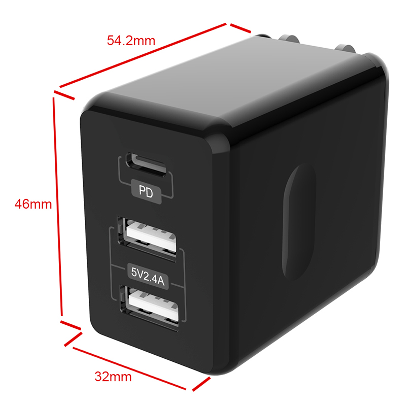
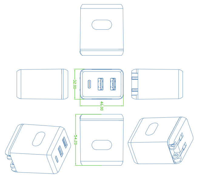
10.Match. Outline Drawing
Wall-mounted (shell color): Black/White
Housing Material (shell material):■PC temperature resistance:120℃
□PC+ABS temperature resistance:95℃
Note: PC material meets the requirements of ball pressure test
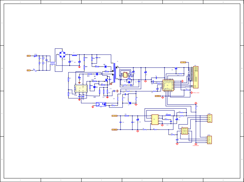
11.Circuit diagram