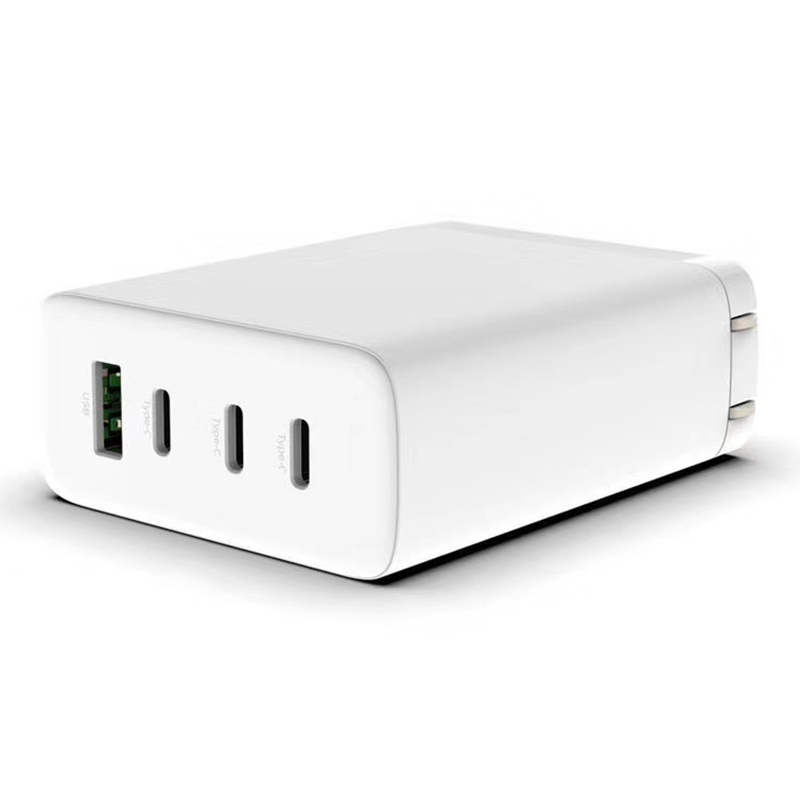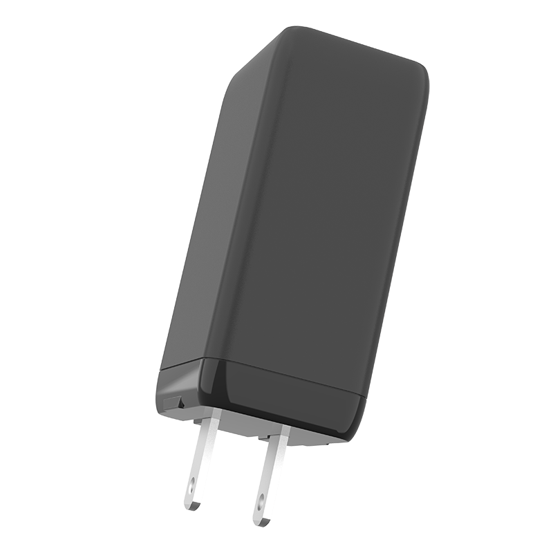


Factory direct supply USB-A Type C port GaN 65W PD Charger
SPECIFICATION FOR APPROVAL
Product Name: GaN 65W Charger
Model No:PQ656P
1、SCOPE:
This product is a consumer product. It can be used for intelligent identification and charging of Bluetooth devices, mobile phones, tablets and other digital electronic products.It is an AC to DC converter with combination of portable travel charger.
1.1. Description
USB CHARGER/ USB SMPS Adaptor(Desk-top)
Open Frame Others
“*”is the company's production and QA must test items.
2、INPUT CHARACTERISTICS:
|
2.1* |
Input voltage range |
90Vac - 264Vac |
|
2.2* |
Normal voltage range |
100Vac - 240Vac |
|
2.3* |
Input frequency range |
47Hz-63Hz |
|
2.4* |
Rated input frequency |
50Hz/60Hz |
|
2.5* |
Maximum input current |
1.6Amax. at full load condition |
|
2.6 |
Surge current(cold start) |
80Amax. @ 264Vac input |
|
2.7* |
Efficiency(Average:20V/3.25A),≧86.0% |
At 115/230Vac.(Test after 30 minutes of work) |
|
2.8* |
No-load power(At 115VAC/230VAC) |
Less than 0.3W |
3、OUTPUT CHARACTERISTICS:
3.1. * Test project
|
Type-C(65W) |
Port output | MIN (V/A) | Standard (V/A) | MAX (V/A) | OCP (A) | Remark |
|
5Voltage |
4.9 |
5.0 |
5.25 |
|
|
|
|
Current |
0.0 |
3.0 |
|
3.2-3.9 |
|
|
|
9Voltage |
8.55 |
9.0 |
9.45 |
|
|
|
|
Current |
0.0 |
3.0 |
|
3.2-3.9 |
|
|
|
12Voltage |
11.4 |
12.0 |
12.60 |
|
|
|
|
Current |
0.0 |
3.0 |
|
3.2-3.9 |
|
|
|
15Voltage |
14.25 |
15.0 |
15.75 |
|
|
|
|
Current |
0.0 |
3.0 |
|
3.2-3.9 |
|
|
|
20Voltage |
19.0 |
20.0 |
21.0 |
|
|
|
|
Current |
0.0 |
3.25 |
|
3.3-4.2 |
|
|
|
注: |
||||||
3.2. * Test project
| Type-C(45W) |
5Voltage |
4.9 |
5.0 |
5.25 |
|
|
|
Current |
0.0 |
3.0 |
|
3.2-3.9 |
|
|
|
9Voltage |
8.55 |
9.0 |
9.45 |
|
|
|
|
Current |
0.0 |
3.0 |
|
3.2-3.9 |
|
|
|
12Voltage |
11.4 |
12.0 |
12.60 |
|
|
|
|
Current |
0.0 |
3.0 |
|
3.2-3.9 |
|
|
|
15Voltage |
14.25 |
15.0 |
15.75 |
|
|
|
|
Current |
0.0 |
3.0 |
|
3.2-3.9 |
|
|
|
20Voltage |
19.0 |
20.0 |
21.0 |
|
|
|
|
Current |
0.0 |
2.25 |
|
2.3-3.0 |
3.3. * Test project
|
USB-A (18W) |
Port output | MIN (V/A) | Standard | MAX (V/A) | OCP (A) | Remark |
|
5Voltage |
4.9 |
5.0 |
5.3 |
|
|
|
|
Current |
0.0 |
3.0 |
|
3.2-3.9 |
|
|
|
9Voltage |
8.55 |
9.0 |
9.45 |
|
|
|
|
Current |
0.0 |
2.0 |
|
3.2-3.9 |
|
|
|
12Voltage |
11.4 |
12.0 |
12.60 |
|
|
|
|
Current |
0.0 |
1.5 |
|
3.2-3.9 |
3.4. *Test project
| Type-C+USB-A | ||
|
Type-C |
USB-A |
TOTAL |
|
65W |
NC |
65W |
|
45W |
18W |
63W |
|
NC |
18W |
18W |
3.5. *Test project
| port output |
Remarks |
| *Single port short circuit protection | Short circuit will enter the burp protection mode, and will automatically recover after the short circuit disappears. |
|
*Start delay time |
2s max at 115Vac to 230Vac input & full load |
|
Rise time |
40ms max at 115Vac input and max load output. |
|
Hold time |
a. 10ms min at full load &115Vac/60Hz input, turn off at worst case
b. 20ms min at full load & 230Vac/50Hz input, turn off at worst case |
| Output Overcharge/Undecharger | 10% max when power supply turn on/off |
| Output Load Transient Response | Output voltage within ±5%, load step from 25% to 50% to 25%, 50% to 75% to 50%, R/S: 0.25A/uS Transient response recovery time :200uS Dynamic response overshoot: ±5% |
| Over voltage protection | The output voltage shall be protected by internal clamped IC |
| *Total output short circuit power | When there is a short circuit, the output power is less than 5W and it will not damage the product. After the short circuit disappears, it will resume automatically. |
3.6 Charging Protocol & Intelligent Identification
|
USB-A (Support ) |
■ QC2.0 ■ QC3.0 |
|
■ BC1.2 ■ Samsung 2.0A ■ APPLE 2.4A |
|
|
■ FCP SCP VOOC |
|
|
PE1.0 PE2.0 |
|
|
AFC Others |
|
|
Type-C (Support ) |
QC2.0 QC3.0 QC4.0 QC4.0+ |
|
PD2.0 PD3.0 PPS |
|
|
BC1.2 Samsung 2.0A APPLE 2.4A |
|
|
FCP SCP VOOC |
|
|
PE1.0 PE2.0 |
|
|
■ AFC Others |
|
| Remarks:PPS by WT01 |
3.7. *Output ripple
| 5V output voltage ripple |
250mV(Max) |
Measurement is done by 20MHz bandwidth oscilloscope and the output paralleled a 0.1uF ceramic capacitor and a 10uF electrolysis capacitor. (Under the condition of rated input and rated output) |
| 9V output voltage ripple |
200mV(Max) |
|
| 12V output voltage ripple |
200mV(Max) |
|
| 15V output voltage ripple |
200mV(Max) |
|
| 20V output voltage ripple | 200mV(Max) |
4.Environment Requirements
4.1. Operating Temperature and Relative Humidity
0℃ to +25℃
10%RH to 90%RH
4.2. Storage Temperature and Relative Humidity
-20℃ to +80℃
5%RH to 95%RH non-condensing @ Sea level shall be low 2,000 meter.
4.3. Vibration
10 to 200Hz sweep at a constant acceleration of 1.0G(Breadth: 3.5mm) for 0.5Hour for each of the perpendicular axes X, Y, Z
4.4. * Drop
At the most dis-advantageous angle, the drop height is 100cm, drop it to the hardwood board 3 times, the pin might be bent and the shell might be injured, but the appearance can not be structurally damaged and it should work normally.
5.Reliability Requirements
5.1. * Burn-in
The product must undergo 100% burn-in before shipment to ensure the quality.
5.2. MTBF
The MTBF shall be at least 30,000 hours at 25℃ max and normal input condition
6.EMI/EMS Standards
6.1. EMI Standards/EMI
|
Certificate |
Country |
Standard |
|
FCC |
USA |
FCC PART 15B |
|
CE |
Europe |
EN55032 EN55024 EN61000-3-2 EN61000-3-3 |
|
C-Tick |
Australia |
AS/NZS CISPR22 |
|
KCC |
Korea |
K32/K35 |
|
PSE |
Japan |
J55032 |
|
CCC |
China |
GB17625.1 |
|
BSMI |
Taiwan |
CNS13438 |
6.2. EMS Standards/EMS
6-2-1 EN 61000-4-2,electrostatic discharge(ESD) requirement
|
Discharge characteristic |
Test Condition |
Test criteria |
|
Air discharge |
+/-8KV |
B |
|
Contact discharge |
+/-4KV |
B |
6-2-2 EN 61000-4-3,radiated electromagnetic field susceptibility(rs)
|
Test level |
Test criteria |
|
3V/m (r.m.s) |
B |
|
80-1000MHz,80%AM(1KHz) sine-wave |
6-2-3 EN 61000-4-4,electric fast transients(burst) immunity requirement
|
Coupling |
Test level |
Test criteria |
|
AC-input |
0.5KV |
A |
|
AC-input |
1KV |
B |
6-2-4 EN 61000-4-5,surge capability requirement
|
Surge voltage |
Test criteria |
|
Common mode +/-2KV |
A |
|
Differential mode +/-1KV |
6-2-5 EN 61000-4-6, Induced radio frequency fields conducted disturbances immunity requirement
|
Test level |
Test criteria |
|
3V |
B |
|
0.15-80 MHz,80%AM(1KHz) |
6-2-6 Assessment criteria
|
Acceptance criteria |
Performance |
|
A |
Agreed operational behavior within the specified limits |
|
B |
Time limited functional diminishment or malfunction during the tests is permitted. The function is self-reactivated by the unit following completion of the tests. |
|
C |
Malfunction is permitted. The function can be reactivated either by reconnection to the mains or by operator intervention.During the test, only the primary protective device is allowed to be damaged. the device can be restored to normal,After the damaged primary protective device is replaced, |
7.* Safety Standards
7.1. Dielectric Strength(Hi-pot)
|
Primary to Secondary: 3000Vac / 5mAMax / 60 second |
7.2. Leakage Current
| 0.25mAmax. at 264Vac / 50Hz |
7.3. Insulation Resistance
| 50MΩ min. at primary to secondary add 500Vdc test voltage |
7.4. Regulatory Standards
|
Certificate |
Country |
Standard |
| UL / cUL
ETL / cETL |
USA | UL62368-1 |
| CE+BS1363 | British | EN62368-1+BS1363 |
| CE | Europe | EN62368-1 |
| SAA | Australia | AS/NZS60950-1 |
| PSE | Japan | J62368 |
| S-Mark | Argentina | IEC60950-1 |
| CCC | China | GB4943 |
| KC | Korea | K60950-1 |
| PSB | Singapore | IEC60950-1 |
|
BSMI |
Taiwan |
CNS14336-1 |
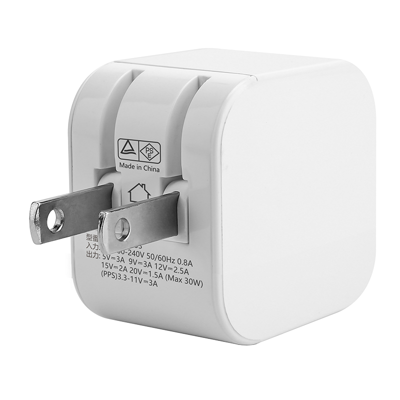
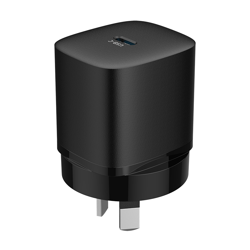
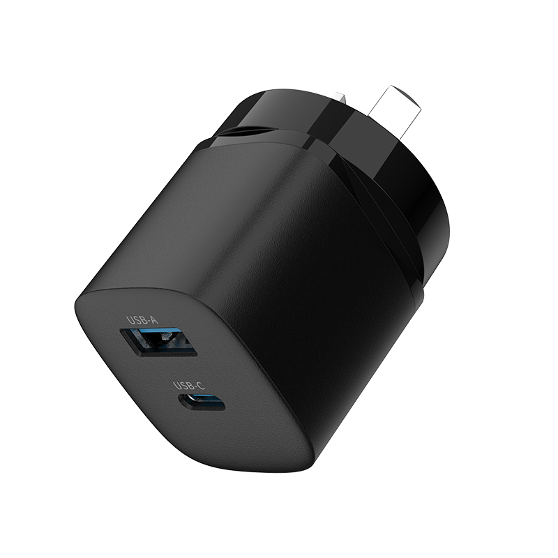
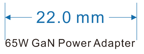
8. Match. Outline Drawing
UL/PSE plug 1C+1A 2ports wall mount (black House)
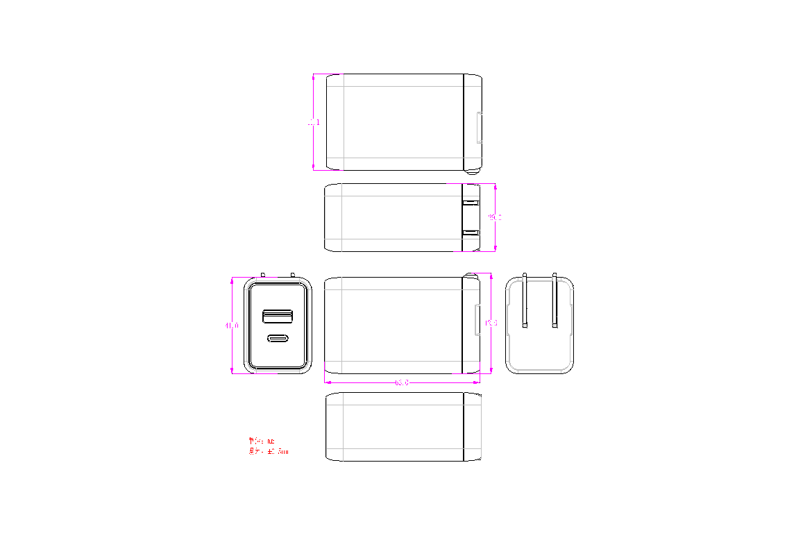
shell material: ■PC temperature resistance 120℃
□PC+ABS temperature resistance 95℃
remark:PC material meets the requirement of spherical pressure test.
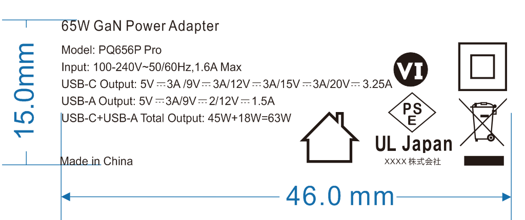
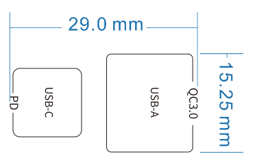
9. I/O Marking Drawing
10. Package Drawing
Pending (Customized Package)